|
||||
| News and Information about the Test of Electronics in Research & Design, Production, Maintenance, and Installation. | ||||

Main MenuNewsletterNews AreaInfo AreaWeblinksProduct Focus |

Readers Top 5 News of last 30 days
Latest Test and Measurement NewsBackground: Synchronizing Frequency, Phase and Time in Mobile xHaul
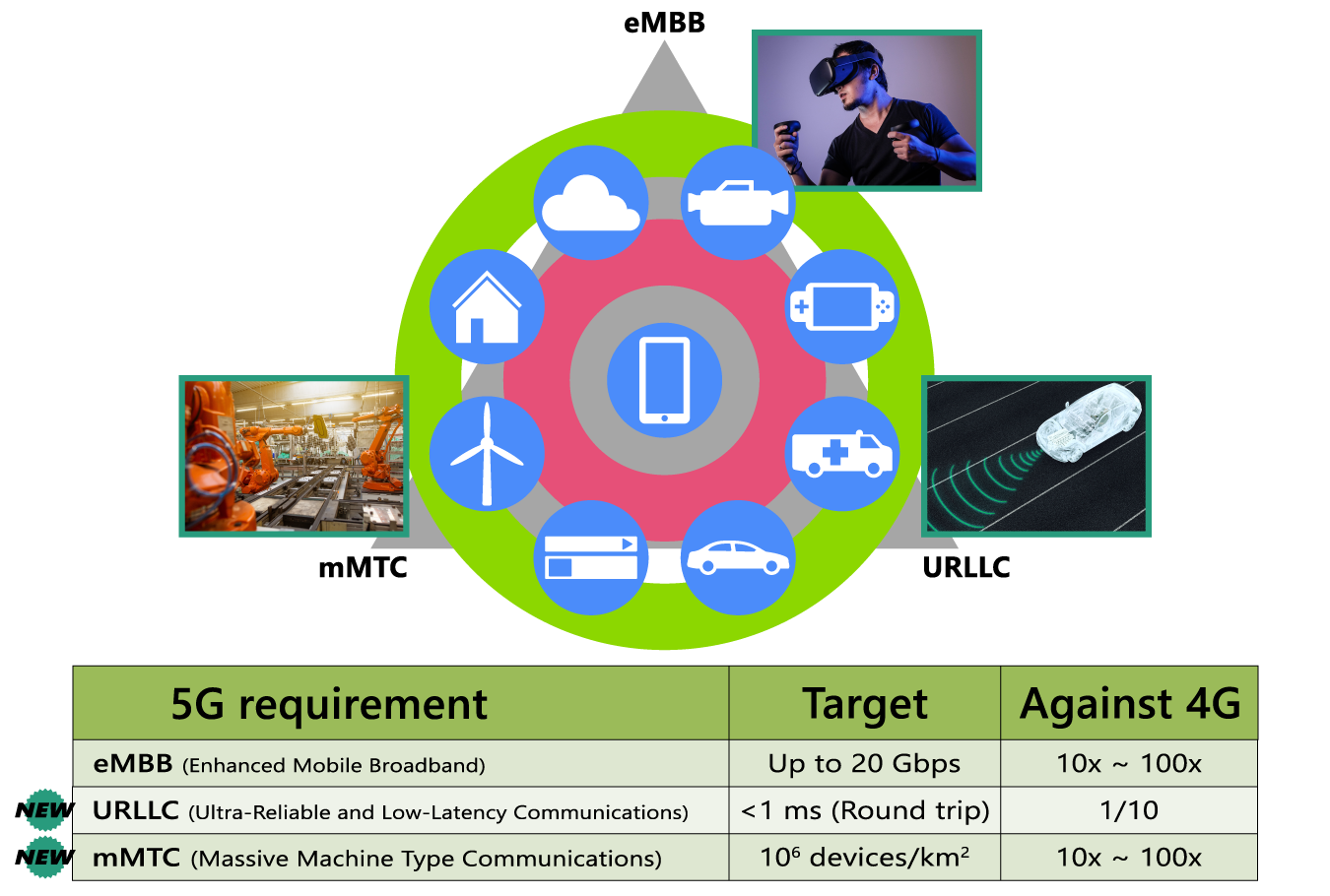
The development of 5G Communications is a game changer enabling Communications Networks to treat traffic in accordance with their priority and bandwidth requirements. Safety critical applications such as automated vehicles or robotics need immediate, fast and guaranteed communications, while others such as texts and e-mails, can accept some delay. Between these are several applications with varying requirements for latency, bandwidth and assured service. Managing the synchronicity of Time, Frequency and Phase is one of the most critical requirements to ensure the network functions correctly.
Figure 1 – 5G Application Categories
Grouped into three main categories, each application requires different support:
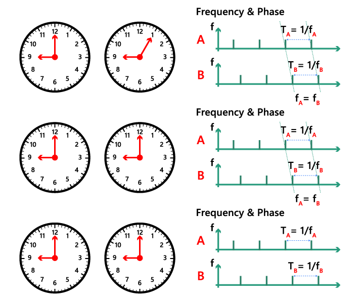
Figure 2 - Time Frequency and Phase
Figure 2 shows three examples of the relationship between Time, Frequency and Phase of two clocks A and B. In each case both clocks measure the passage of time at the same rate, so the frequency is synchronized. in the top example, the two clocks show a different time and in the corresponding “Frequency & Phase” diagram to the right, there is a Phase Delay from A to B. While the passage of time progresses correctly, the announced time is incorrect, and the strike of each second isn’t aligned. In the middle example the time of clocks A and B agree, but there is still a Phase Error between the two clocks. The strike of each second is still not aligned. For the Communications Network to function correctly and deliver the guaranteed level of service required for URLLC, certain operations must happen at exactly the right time. Therefore, Time, Frequency and Phase must all be synchronised as shown in the third example. Most mobile communications backhaul networks use a combination of Synchronous Ethernet (Sync E) and IEEE 1588 Precision Time Protocol (PTP) to manage the synchronization of Frequency, Time and Phase. Sync ESync E is defined in the ITU-T G.8261 Standard for timing and synchronization aspects in packet networks. It outlines the requirement for transferring a clock signal, traceable to an external clock standard, along with the data over the Ethernet physical layer.
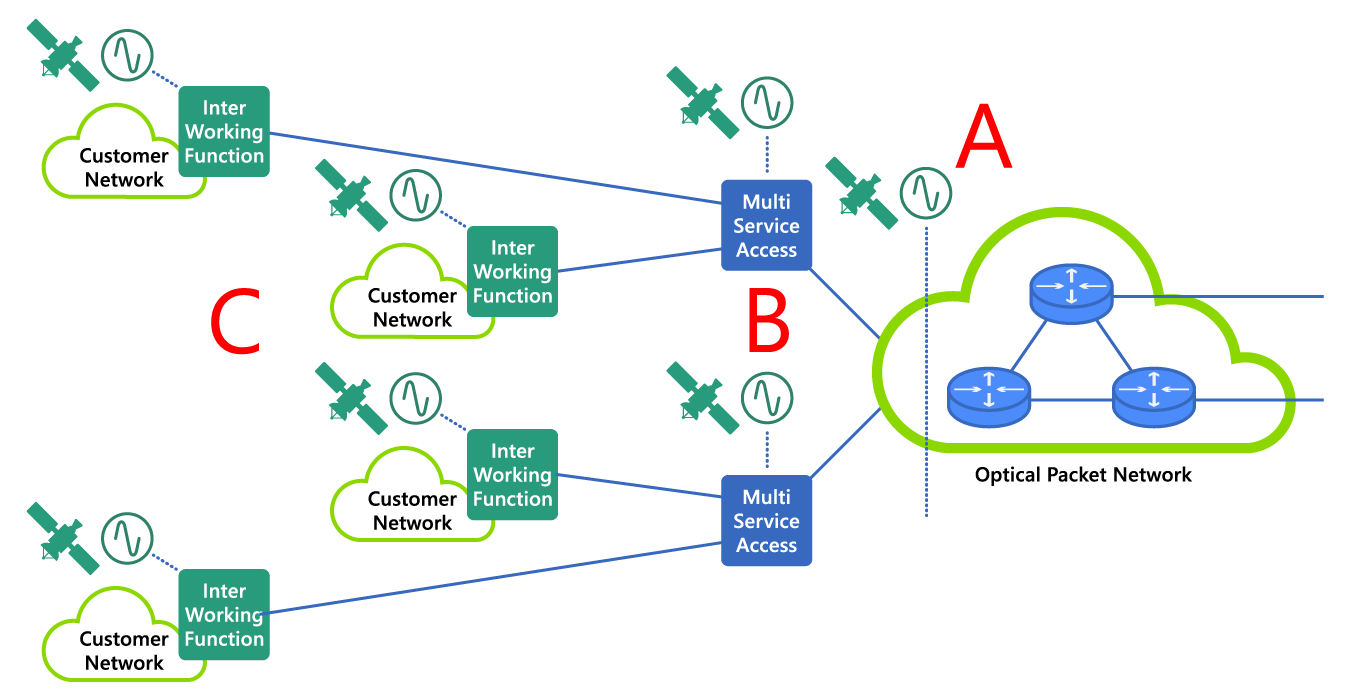
Figure 3 – Example of Sync E Network Topology
In typical Sync-E architectures, a Primary Reference Clock will be in one of three positions, either at the Core, at Multi-Service Access points or at the Inter-working Function closer to the customer’s equipment. Providing that the Ethernet Network Equipment can transfer the clock signal, having the Primary Reference Clocks at the core reduces the number of clocks and makes it easier to maintain network synchronization. Deploying Primary Reference Clocks closer to the customer can increase the number of clocks, making it possible to ‘see’ more than one clock. To determine which is the Primary Reference Clock, we need information about the clock’s status, its accuracy and clock type. A Synchronization Status Message (SSM), with information about the stratum clock type and its quality level, forms part of an Ethernet Synchronization Messaging Channel (ESMC). ITU-T G.8264 requires the ESMC to be transmitted at regular intervals, typically once per second, and provides the information needed to maintain good synchronization. If the quality level changes, an ESMC is sent immediately to announce the change. Checking to see that the correct quality levels are sent in the ESMC at regular intervals is critical as failure in this communication can lead to the network failing. PTPSync E only addresses Frequency Synchronization while modern communications systems such as 5G also need Time and Phase synchronization. These requirements are met by Precision Time Protocol (PTP). PTP distributes synchronized time signals to network equipment, allowing small corrections to calculated Time Error (TE), and is used in a range of applications, including Telecom and Cellular Communications, where synchronization quality must be confirmed at every cell site.
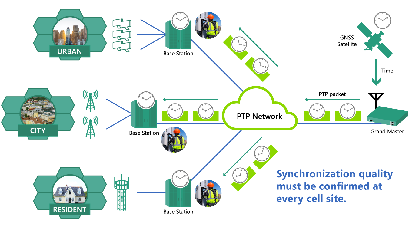
Figure 4 - Example of PTP Distribution
Because not all applications require the same degree of accuracy, different PTP profiles provide appropriate standard definitions for different applications. Two profiles are defined for PTP in telecom networks. G.8275.1, used for phase/time synchronization with full timing support from the network, assumes that Boundary Clocks or Transparent Clocks are deployed in every node. G.8275.2 supports synchronization where only partial timing can be maintained from the network. It describes how PTP timing should be transferred when the network equipment cannot forward synchronized data, for instance where buffering occurs. The protocol is a series of packets that transfer information about time and which form the basis for any TE correction required. Each network termination assumes a Master / Slave relationship in a hierarchy with the Grand Master Clock (T-GM) at the top. Most operators employ a two-step PTP mode, which differs from one-step by including a Follow Up message, as shown below.
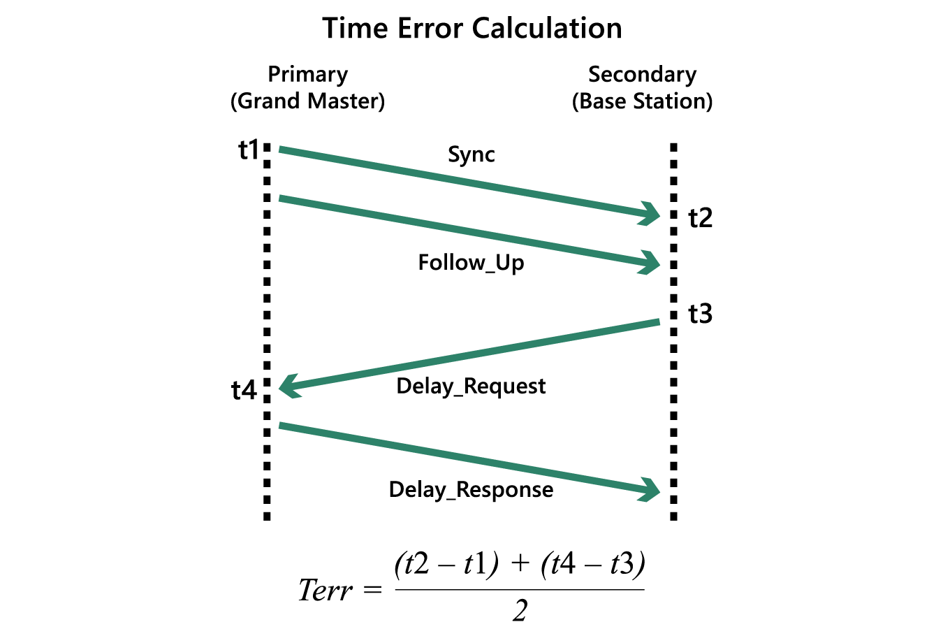
Figure 5 – Two Step PTP Protocol Message Flow
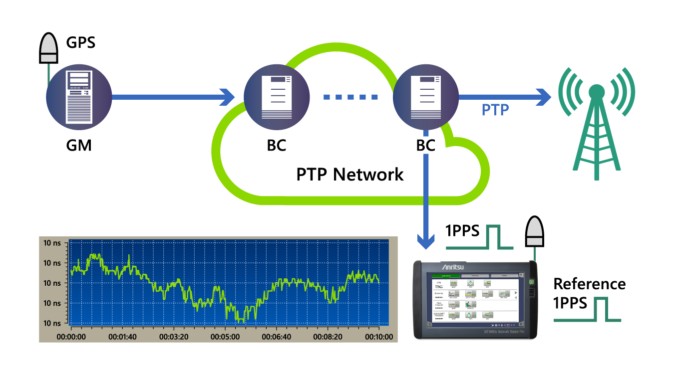
The Grand Master sends a “Sync” message to the Slave containing “Time of Day” recorded by the Grand Master. The Grand Master then sends a “Follow Up” message with a hardware timestamp giving the exact time the previous Sync Message was transmitted. The slave will use this message to synchronize its current time more accurately. The Slave then sends a “Delay Request” to the Grand Master. On receipt of the “Delay Request”, the Grand Master immediately sends a “Delay Response” to inform the Slave what time the “Delay Request” was received. The Slave then calculates the Round-Trip Delay, from the difference between the “Delay Request” and “Delay Response” messages. The Slave now adjusts its own time to synchronize to the Grand Master. When the clocks are within one second of each other, the Grand Master instructs the Slave to adjust its frequency to maintain accuracy. 1PPSA Global Navigation Satellite System (GNSS) disciplined (synchronized to GNSS) T-GM acts as the PRTC and provides the reference time from which the rest of the network is synchronized. The reference time reaching the receiver will be affected by propagation delay through the antenna cable from the GNSS antenna. The T-GM compensates for the antenna cable propagation delay at approximately five nanoseconds per meter. A T-GM usually provides a separate precise One Pulse Per Second (1PPS) time reference. This relates directly to the frequency and phase of the clock and can be measured to confirm the T-GM is operating and set up correctly. It is recommended to first complete measurements of the 1PPS, since an error at the T-GM would result in the whole network being out of sync.
Figure 6 – Example 1PPS result
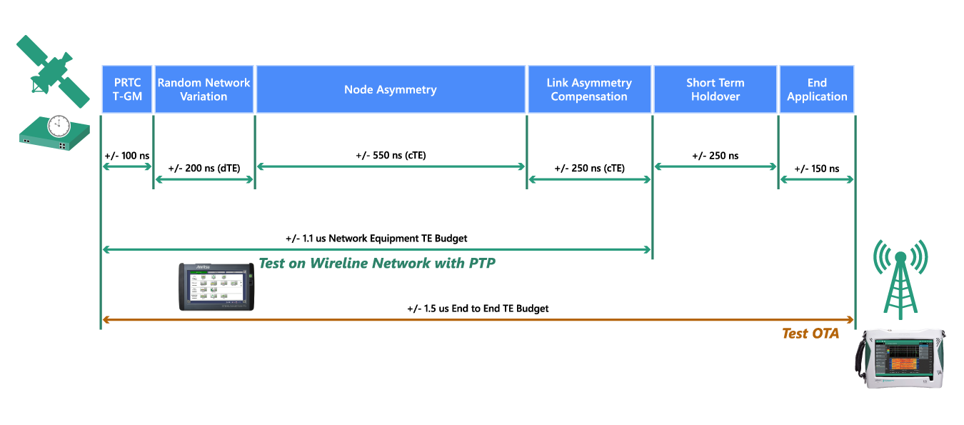
Time BudgetTE accumulates as the clock signal travels from the Primary Reference Time Clock (PRTC) through the network. TE budgets are specified in the ITU-T G.8271.1 standard, with allowances being made for it at different stages in the network.
Figure 7 - ITU-T G.8271.1 standard TE budgets
A time of 400 nanoseconds is reserved to account for short term holdovers and the TE of the end application, from the radio equipment to the User Equipment (UE), i.e. smart phone, tablet, etc. A maximum of 1.5 micro-seconds TE is allowed between the PRTC and the UE, so the network to the radio equipment must support a maximum of 1.1 micro-seconds. The diagram above shows how the TE budget is provisioned through the network. Over the Air Measurement of TE will give a total TE for the installation. However, for confident TE management, it is necessary to test with equipment that emulates integral components of the network. Sync TestTesting synchronicity in mobile backhaul networks requires test equipment with an internal clock source, which is disciplined to GNSS and accurate to the nanosecond level. A Rubidium or Caesium oscillator is the usual method used. The tester then needs to emulate the network equipment to test Sync-E and PTP timing functions in both the Master and Slave modes.
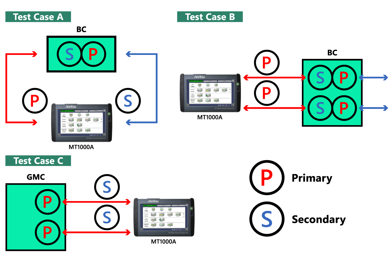
Figure 8 – Test Case Master / Slave Applications
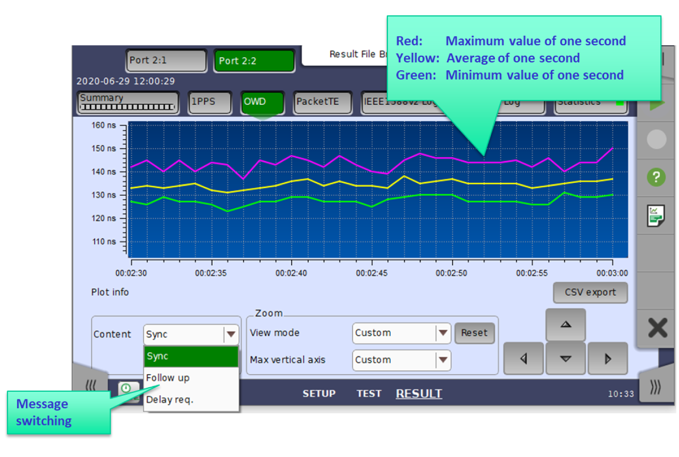
In test case “A” the test equipment, with one port, emulates the Grand Master Clock, while simultaneously measuring the sync performance of the device/network, with its second port acting in slave mode. If these point are widely separated, two testers can be used, with both instruments synchronized to GNSS. Test Case “B” shows both ports set to emulate the Grand Master, which can be useful during network installation, or in a lab, where a Primary Reference Clock cannot be easily accessed. Once network installation is complete and time sync is provided by the Grand Master, synchronization must be tested throughout the network, first verifying that correct settings are entered for the Grand Master. The time management processes are then tested to determine correct functioning, and that frequency, phase and time are synchronized according to the standards. This can be seen in Test Case “C”. OWDTo make Sync measurements, the tester emulates a Slave clock, allowing the system clock to act as the Master. The tester calculates the difference in time between the PTP message being sent and received from accurate timestamps included in the PTP packets. This can be observed as One-Way-Delay (OWD). Real time OWD is calculated for each Sync, Follow Up and Delay Request message. The result shown is for a typical PTP repetition rate of 16 times per second and plotted over time. The PTP process completes several times each second. The repetition rate is commonly 16 but can be set differently.
Figure 9 – OWD Result Screen
In the tester screen above, the red line shows the maximum value observed of the sixteen PTP cycles, the green line shows the minimum and the yellow line is the calculated average for all sixteen cycles during that second. Results are recorded and can also be exported in CSV format for further analysis. The OWD across the Sync and Delay Request messages includes the propagation delay of the Ethernet cables, which accounts for approximately five nanoseconds per meter of delay added to the measurement. So, constant Packet Time Errors cTE1 and cTE4 are calculated for the result of OWD minus the propagation delay of the Ethernet cable. Packet Time Error Summary
Figure 10 – PTP Result Summaries
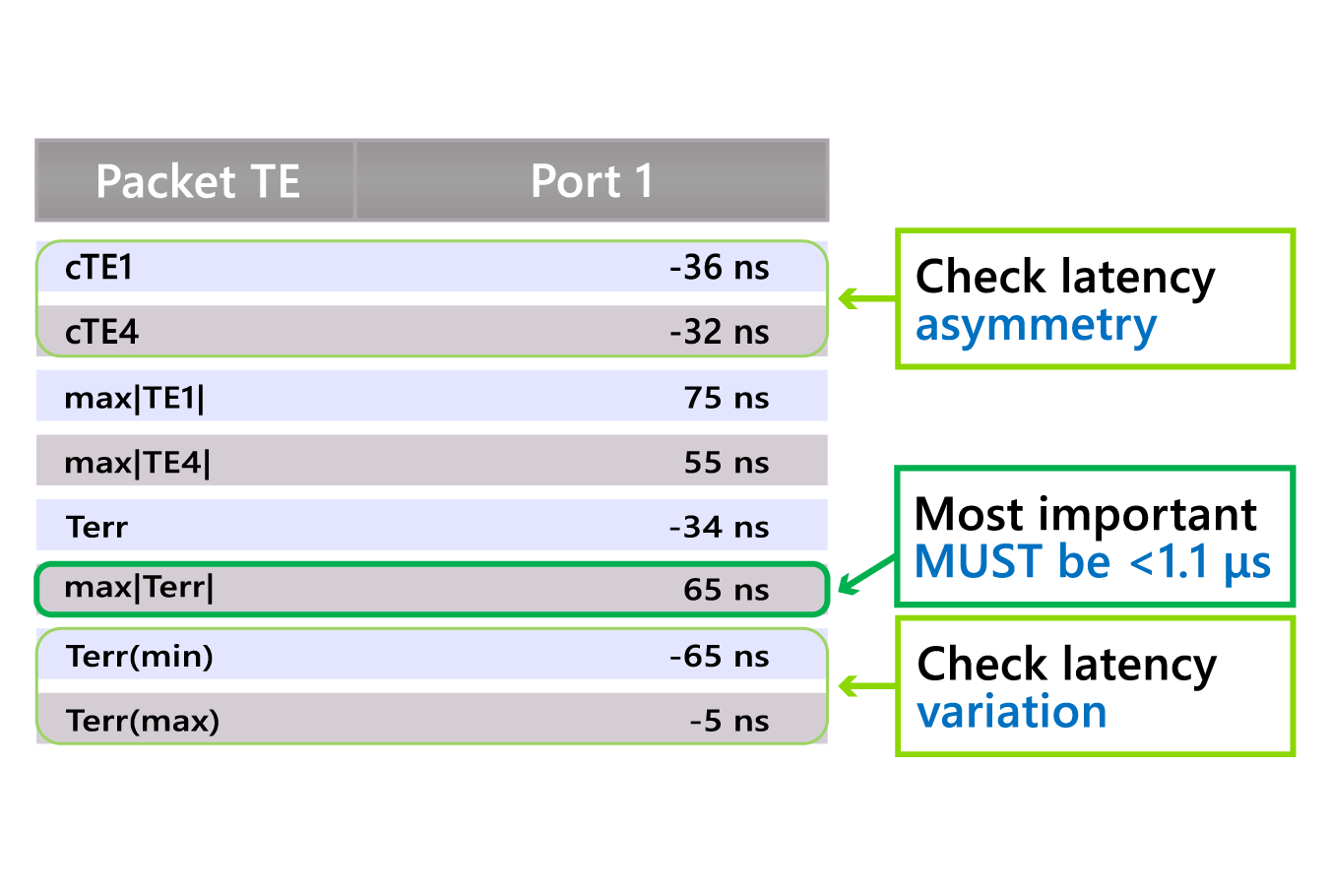
A summary screen showing the top-level results allows quickly verification of good Sync performance and flags up any issues. The most important value is the maximum time error, max|Terr|, showing the worst case. Constant time errors cTE1 and cTE4 are equal to latency, in each direction and gives a view of asymmetry, so we want to see values that are almost equal. IEEE 1588 Network Summary
Figure 11 - IEEE 1588v2 summary screen
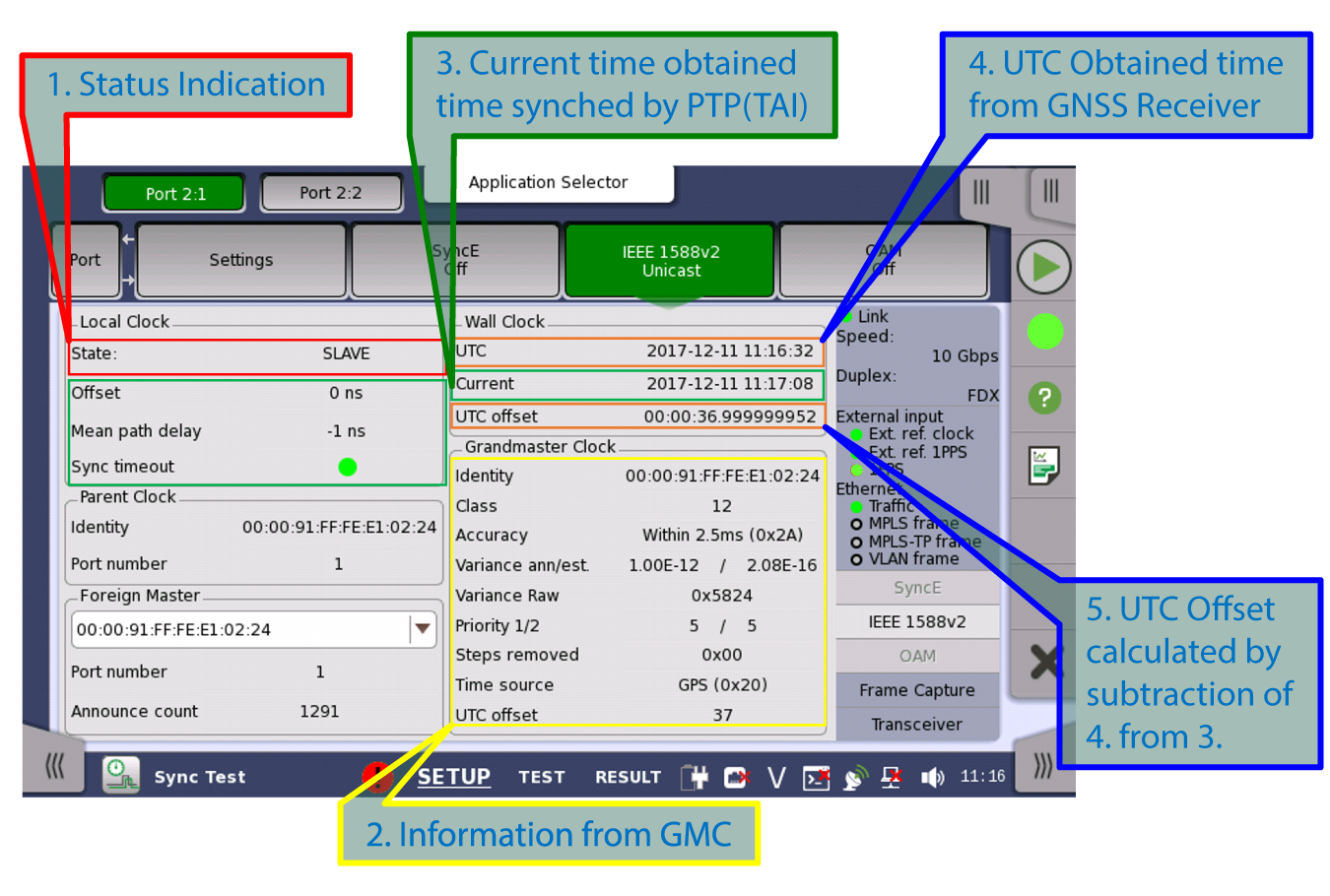
The tester IEEE 1588v2 summary screen provides acquired information about different clocks in the network. It shows the MAC addresses of the Grand Master, Parent and Foreign master clocks, allowing the operator to verify that time is derived from the correct place. Further information about the Grand Master Clock, its clock class, priority, accuracy, etc., is provided. The status of the Local Clock, its offset and Mean Path Delay verifies the sync performance, while a Sync Timeout LED showing green indicates that the local clock is in sync with the Grand Master. Correction for the current Universal Time Clock (UTC) needs to be made. A PRTC needs to be corrected to UTC, currently 37 seconds, and the correct setting verified. Author: By Andrew Cole, Application Engineer, Anritsu www.anritsu.com/ Related Articles: |

Upcoming Events More events...
Tag CloudOscilloscope
JTAG
Boundary Scan
Goepel
PXI
Rohde & Schwarz
Tektronix
Keysight
AOI
Anritsu
National Instruments
Inspection
Teledyne LeCroy
Aeroflex
LTE
Yokogawa
AXI
Spectrum Analyzer
Keithley
In-Circuit-Test
Signal Analyzer
Automotive
EMC-Test
Signal Generator
Advantest
Multitest
B&K Precision
Corelis
Power Supply
SPI
Flying Prober
Teseq
Cognex
Switching
Teradyne
Viscom
Pickering
Fluke
GAO Tek
PCIe
|
||
|
© All about Test 2018 |
||||
 How to resolve AdBlock issue?