 |

Main Menu
Newsletter
News Area
Info Area
Weblinks

Eye Diagrams Capabilities for Serial Trigger and Decode Solutions
 01 July 2016 - Teledyne LeCroy expanded the Serial Data Analysis capabilities for its oscilloscope solutions by introducing as first oscilloscope manufacturer Eye Diagram capabilities in the new TDME Serial Bus options. Eye diagram mask testing and mask failure locator can be used to identify physical layer anomalies.
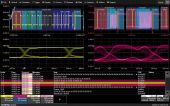
An eye diagram of packetized low-speed serial data signal can be displayed rapidly without additional setup time. Eye parameters can be used to quantify system performance and apply a standard or custom mask to identify anomalies. Mask failures can be indicated and can force the scope into Stop mode.
Up to four serial data signals can be decoded and displayed as eye diagrams at one time. These can be different protocols, or the same protocol measured at different points (e.g., transmits and receive, different nodes, or different standard-defined test points). You can apply a user-defined filter to each eye diagram to only display specific signals in the eye.
The signal quality of physical layer can be qualified in the eye by applying parameters for Eye Height, Eye Width, and Number of Mask Failures. Some packages (e.g. FlexRay TDMP) go a step further and include additional measurements defined in the standard.
A user-defined or pre-defined mask may be added to the eye diagram so as to objectively evaluate if the physical layer signal intrudes too far into the eye opening. Apply a filter to include or exclude specific messages from the Eye so as to determine failure source (e.g., messages from a specific node or with a specific ID). Mask failures are indicated with a red circle and can be displayed in a table. Touch the failure table to open a zoom of the failed area for further inspection.
Some standards, due to their speed or nodal complexity, provide specific guidance on what eye diagrams or measurements should be made and exactly how they should be performed. FlexRay and MIPI DPHY are examples. In these cases, the Eye Diagram (“E”) capability is augmented with additional specialized “P” capability (for Physical Layer Measurements), per the standard In these cases, the “E” capabilities previously described are also available.
Eye Diagram is available for the following standards: I2C, SPI, UART RS-232, CAN, CAN FD, FlexRay, LIN, ARINC429, MIL-STD-1553, USB 2.0, 8b/10b, LPDDR2, DDR2, DDR3;, D-PHY/CSI-2/DSI, M-PHY, NRZ.
www.teledynelecroy.com/

Upcoming Events
More events...
See our Trade Show Calendar
Click here
Tag Cloud
© All about Test 2018